Engineering Design Graphics
Engineering Design Graphics

Engineering Design Graphics – R. Hewitt, EngineeringTechnology.org

Expanded Outline

I. Introduction to Engineering Graphics
A. Overview of Engineering Graphics in Engineering Technology
B. Importance of Working Drawings in Engineering Technology
C. Purpose of Working Drawings
D. Overview of Engineering Drawing Conventions and Standards

II. Blueprint Reading
A. Understanding Blueprint Reading Fundamentals
B. Types of Engineering Drawings
C. Blueprint Reading Techniques and Best Practices

III. Scales and Units of Measurement
A. Introduction to Scales and Units of Measurement
B. Common Units of Measurement for Engineering Drawings
C. Use of Scales in Engineering Drawings
D. Scaling Techniques for Accurate Measurements

IV. Drawing Instruments
A. Overview of Common Drawing Instruments
B. Use of Drawing Instruments in Engineering Drawings
C. Best Practices for Care and Maintenance of Drawing Instruments

V. Alphabet of Lines
A. Introduction to the Alphabet of Lines
B. Types of Line Conventions Used in Engineering Drawings
C. Use of the Alphabet of Lines in Working Drawings

VI. Lettering
A. Introduction to Lettering in Engineering Drawings
B. Types of Lettering Styles Used in Engineering Drawings
C. Best Practices for Lettering in Working Drawings

VII. Geometry Review
A. Overview of Basic Geometric Concepts
B. Types of Polygons, Circles, and Curves
C. Use of Geometry in Engineering Drawings

VIII. Geometric Construction
A. Introduction to Geometric Constructions
B. Types of Geometric Constructions Used in Engineering Drawings
C. Geometric Construction Techniques for Engineering Drawings
D. Best Practices for Geometric Construction in Working Drawings

IX. Orthographic Projection
A. Introduction to Orthographic Projection
B. Types of Orthographic Projections Used in Engineering Drawings
C. Orthographic Projection Techniques and Best Practices
D. Applications of Orthographic Projection in Working Drawings

X. Standard Views
A. Overview of Standard Views in Engineering Drawings
B. Types of Standard Views Used in Working Drawings
C. Best Practices for Producing Standard Views in Engineering Drawings

XI. Section Views
A. Overview of Section Views in Engineering Drawings
B. Types of Section Views Used in Working Drawings
C. Best Practices for Producing Section Views in Engineering Drawings

XII. Auxiliary Views
A. Introduction to Auxiliary Views in Engineering Drawings
B. Types of Auxiliary Views Used in Working Drawings
C. Best Practices for Producing Auxiliary Views in Engineering Drawings

XIII. Dimensioning
A. Overview of Dimensioning in Engineering Drawings
B. Types of Dimensioning Used in Working Drawings
C. Dimensioning Techniques and Best Practices for Engineering Drawings
D. Use of Dimensioning in Orthographic Projections and Section Views

XIV. Material Specifications
A. Introduction to Material Specifications in Engineering Drawings
B. Types of Material Specifications Used in Working Drawings
C. Best Practices for Incorporating Material Specifications in Engineering Drawings

XV. Pictorial Views
A. Overview of Pictorial Views in Engineering Drawings
B. Types of Pictorial Views Used in Working Drawings
C. Best Practices for Producing Pictorial Views in Engineering Drawings

XVI. Descriptive Geometry
A. Introduction to Descriptive Geometry
B. Orthographic Projections
C. Intersections of Planes and Solids
D. Development of Surfaces
E. Applications of Descriptive Geometry in Working Drawings

XVII. Contour Maps
A. Cut and Fill
B. Strike and Dip
C. Outcrop and Dip Direction

The Engineering Design Process

The Engineering Design Process
The engineering design process is a series of steps that engineers use to create solutions to problems. It is a structured approach to problem-solving that involves identifying a problem, defining the problem, generating potential solutions, evaluating those solutions, selecting the best solution, and implementing and testing that solution. The engineering design process is iterative, meaning...

Drawing Instruments

Drawing Instruments
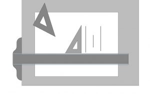
Today, engineering drawings are very seldom constructed by hand. CAD technology is the universal choice in industry. However, it is useful to include a discussion of the instruments that were historically used for this purpose. Manual drafting is an appropriate way teach the fundamentals of engineering graphics. The most important concepts of engineering graphics are...

Line Conventions and Lettering

Line Conventions and Lettering
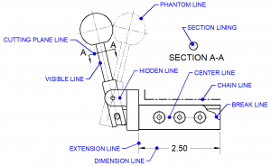
Engineering drawings are a critical part of the design and manufacturing process, providing detailed information on dimensions, materials, and tolerances. To ensure clear and consistent communication, drawings must adhere to specific conventions for line types and lettering. These conventions are defined by the American Society of Mechanical Engineers (ASME) in the Y14.2 standard. Proper use...

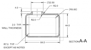
Dimensioning

Dimensioning
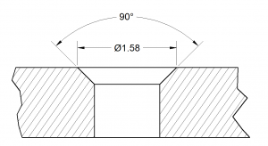
Dimensioning is a crucial aspect of engineering drawings, which plays an essential role in communicating design specifications and requirements to manufacturers, engineers, and other stakeholders. Essentially, dimensioning refers to the process of specifying the exact size, shape, and location of different parts and features on an engineering drawing. Dimensioning is vital in the engineering industry...

CAD – Siemens NX

CAD - Siemens NXNX Tutorials  NX Tutorial Video 1 – User Interface NX Tutorial Video 2 – Drafting Workflow NX Tutorial Video 3 – Expressions Editor NX Tutorial Video 4A – Sketch & Revolve NX Tutorial Video 4B – Datums and Features NX Tutorial Video 4C – Pattern Feature NX Basic Modeling Workflow  NX Master...

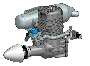
M40 Glow Plug Engine

M40 Glow Plug Engine
M40 Glow Plug EngineCrankcase Group  Crankcase Connecting Rod Crankshaft Wrist Pin Piston Cylinder Liner Head Gasket Cylinder Head Glow Plug Cover Plate Cover Plate Gasket Fuel System  Carburetor Assembly  Carb Body Assembly  Carb Body Jet Molding Throttle Arm Carb Rotor Carb Hardware Fuel Line Needle Valve Assembly  Valve Body Assembly  Valve Body Overmolding Valve Body...

Design Problems

Design Problems
Fostering Practical Application in Engineering Graphics The design problems section bridges the gap between theoretical concepts and real-world applications. Aspiring engineers and designers will find this section useful for honing their problem-solving skills and applying the principles of engineering graphics to practical scenarios. Through a collection of engaging exercises and challenges, this section encourages students...

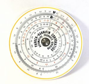
Graphical Calculators and Nomograms

Graphical Calculators and Nomograms
Graphical Calculators: Graphical calculators are electronic devices designed to perform a wide range of mathematical computations while also providing visual representations of mathematical functions and data. These calculators typically feature high-resolution screens that allow users to input equations, graph functions, and analyze data with ease. They are commonly used in educational settings, scientific research, engineering,...
The Engineering Design Process

The Engineering Design Process

The engineering design process is a series of steps that engineers use to create solutions to problems....
Engineering Design Assumptions

Engineering Design Assumptions

The engineering design process involves making a series of decisions to create a product that meets...
Design Methodologies

Design Methodologies

Design methodologies are systematic approaches to the design process that help ensure that products...

Concurrent Design

Concurrent design is a process that involves the simultaneous design and development of multiple aspects...
Risk Mitigation through Design

Risk Mitigation through Design

Engineering design involves creating innovative and effective solutions to various problems. However,...

FMEA - Failure Modes and Effects Analysis

FMEA (Failure Mode and Effects Analysis) is a methodology used to identify and mitigate potential failures...

Design Perspicuity

In engineering design and CAD (Computer-Aided Design), "perspicuity" refers to the fundamental principle...

Engineering Design - Example Projects

The examples included here demonstrate various elements of the engineering design process.
Automated Hydrogen Generator

Automated Hydrogen Generator

This project automates the electrolysis process of hydrogen generation. The result is a system that...
Drawing Instruments

Drawing Instruments

Today, engineering drawings are very seldom constructed by hand. CAD technology is the universal choice...