Dimensioning

Dimensioning is a crucial aspect of engineering drawings, which plays an essential role in communicating design specifications and requirements to manufacturers, engineers, and other stakeholders. Essentially, dimensioning refers to the process of specifying the exact size, shape, and location of different parts and features on an engineering drawing.

Dimensioning is vital in the engineering industry as it ensures that the final product meets the required standards and specifications. It helps to minimize errors and inaccuracies during the manufacturing process, thereby reducing the risk of costly mistakes and delays. Additionally, it enables engineers and manufacturers to ensure that the final product meets the customer’s expectations, which is critical in today’s competitive market.

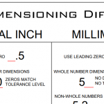
To ensure that engineering drawings are dimensioned correctly, various industry standards must be followed. For example, the American Society of Mechanical Engineers (ASME) has developed a set of guidelines that outline the proper practices for dimensioning engineering drawings. These guidelines include specifying the appropriate units of measurement, ensuring clear and concise labeling, and avoiding ambiguity or confusion when dimensioning features.

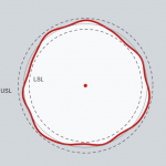
Another important aspect of dimensioning is tolerancing, which involves specifying the allowable deviation or variation from the specified dimensions. Tolerancing is crucial in ensuring that the final product is functional and reliable, as it allows for the natural variation that can occur during the manufacturing process.

Geometric Dimensioning and Tolerancing (GD&T)

Geometric Dimensioning and Tolerancing (GD&T) is a system of symbols and standards used in engineering drawings and models to specify the required form, size, orientation, and location of parts and features.

Ordinate Dimensions

Ordinate Dimensions
Ordinate dimensions, also known as baseline dimensions, are a type of dimensioning system used in technical drawings and engineering design to define the location of features or objects relative to a common reference axis or baseline. Instead of providing individual dimensions for each feature's location, ordinate dimensions reference a common starting point or origin, often...

Inch Vs. Millimeter Dimensioning Differences Chart

Inch Vs. Millimeter Dimensioning Differences Chart
There are some important differences between how inch and millimeter dimensions are formatted. This chart is a summary of these sections from ASME Y14.5-2018. Dimensioning-DifferencesDownload

Geometric Dimensioning and Tolerancing (GD&T)

Geometric Dimensioning and Tolerancing (GD&T) is a system of symbols and standards used in engineering...
Form Tolerances

Form Tolerances

Form tolerances limit the amount of deviation from a perfect geometric form, such as a line, circle,...
Roundness or Circularity

Roundness or Circularity

Circularity is used to control how circular a feature, like a hole or a cylindrical surface, must be....
Straightness

Straightness

Straightness applies in one direction only. I applies in the direction where the controlled area is...
Ordinate Dimensions

Ordinate Dimensions

Ordinate dimensions, also known as baseline dimensions, are a type of dimensioning system used in technical...
Inch Vs. Millimeter Dimensioning Differences Chart

Inch Vs. Millimeter Dimensioning Differences Chart

There are some important differences between how inch and millimeter dimensions are formatted. This...