Above all else, an engineering documentation must be clear. All text on engineering drawings should be simple and readable. Most older texts (and the ANSI Standard) refer to the standard style of lettering as single-stroke Gothic. This term is somewhat archaic today, but what it means is simply a style of text that does not have serifs or...

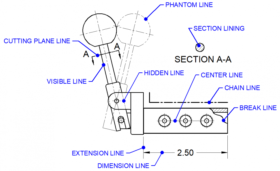
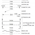
In engineering drawings, lines of different types and widths are used to convey important information about the object being depicted. ASME Y14.2 provides guidelines for the types of lines that should be used in different situations, as well as the appropriate line widths. In addition to line type, line width is also an important factor...

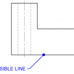
In an engineering drawing, visible lines are the thick, solid lines that represent the visible edges and boundaries of an object or part. Their purpose is to clearly and accurately depict the shape and size of the object, as well as to distinguish it from any hidden or non-visible features. Visible lines are typically drawn...

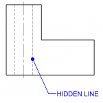
Hidden lines are used in engineering drawings to represent features that cannot be seen in a particular view but are necessary to fully define the part or assembly. These features are typically inside the object or obscured by other surfaces. Hidden lines are represented by a series of short dashes, evenly spaced, with the first...

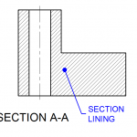
Section lining is a method of representing internal features of an object in an engineering drawing. This technique involves the use of parallel lines drawn at a 45-degree angle to the object being depicted, with section lining of adjacent features drawn in the opposite direction. Avoid aligning section lines with features and edges. Section lining...

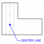
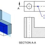
Center lines are an important element of engineering drawings that are used to represent the axis of symmetry for a part or assembly. These lines are drawn as long, thin dashed lines and are used to indicate the center point of cylindrical features, such as holes or shafts. Center lines are used to help ensure...

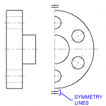
Symmetry lines are used to indicate an axis of symmetry when a partial view is shown. Symmetry lines pairs of short parallel lines located on the ends of the centerline that defines the axis of symmetry.

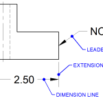
Dimension, extension, and leader lines play crucial roles in providing essential measurements, indicating features, and directing attention to specific areas of interest. Understanding these lines is vital in the interpretation and creation of technical drawings. Dimension Lines Dimension lines are used to indicate the size and location of features in an engineering drawing. They provide...

A cutting plane represents an imaginary plane or section where an object is cut to reveal its internal details. It acts as a visual indicator, helping viewers understand the hidden features within a solid object or component. The cutting plane line is typically drawn as a thick line with evenly spaced dashes, which distinguish it...
Above all else, an engineering documentation must be clear. All text on engineering drawings should...
Lettering Practice - Alphabet Download
Lettering Practice - Paragraph Download
In engineering drawings, lines of different types and widths are used to convey important information...
In an engineering drawing, visible lines are the thick, solid lines that represent the visible edges...
Hidden lines are used in engineering drawings to represent features that cannot be seen in a particular...
Section lining is a method of representing internal features of an object in an engineering drawing....
Center lines are an important element of engineering drawings that are used to represent the axis of...
Symmetry lines are used to indicate an axis of symmetry when a partial view is shown. Symmetry lines...
Dimension, extension, and leader lines play crucial roles in providing essential measurements, indicating...
A cutting plane represents an imaginary plane or section where an object is cut to reveal its internal...