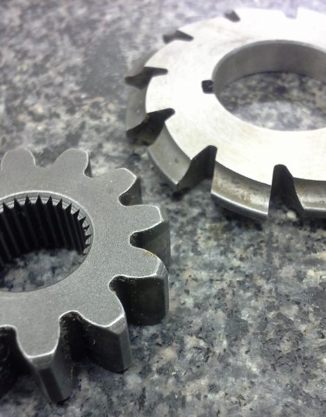
Machining gears is a common manufacturing process used to create gears for various applications, including automotive, aerospace, and industrial machinery. This process involves using milling machines or similar equipment to cut gear teeth into a workpiece, typically made of metal. In this article, we will discuss the basics of machining gears, including the use of involute cutters, indexing methods, and the production of helical gears.

An involute cutter is a cutting tool used in gear manufacturing that has teeth shaped like the involute curve. The involute curve is a mathematical curve that has the unique property of being able to mesh perfectly with other gears with the same pressure angle. The involute cutter is used to cut the teeth of a gear into a workpiece, producing a smooth and accurate gear profile.
Indexing methods are critical when machining gears, as they ensure that the gear teeth are cut at the correct spacing and angle. There are various indexing methods used in gear manufacturing, including dividing heads and rotary tables. Dividing heads are used to rotate the workpiece a specific number of degrees between each cut, while rotary tables can be used to make cuts at precise angles.
In the production of helical gears, a different approach is used to ensure the proper gear tooth profile. A helical gear has teeth that are cut at an angle, rather than perpendicular to the gear’s axis. To produce these gears, a special milling machine is used that can tilt the cutting tool at the correct angle. The indexing method used for helical gears is typically a helical index head, which can rotate the workpiece and cutter simultaneously to produce the angled teeth.
