This NX video tutorial series is designed to provide a solid foundation in using Siemens NX software for engineering and design tasks. The series starts with an introduction to Siemens NX, guiding users through workspace setup and interface navigation. Basic modeling skills are covered, including sketching techniques and creating 3D models using fundamental operations. Advanced...
Sketch Fully define sketch Extrude (or Revolve, Sweep) Add Detail Features Document with Drafting Application See: Master Model Concept Use in Assemblies Concurrent Design & PLM Design Tooling Program CNC Machines Create Derivative Designs
https://youtu.be/GUaa97tALxE View Controls Mouse Controls Fit Clipping Planes Edit Object Display Section Views Show/Hide Feature Suppression Layer Settings & Standards View-ControlsDownload PRT
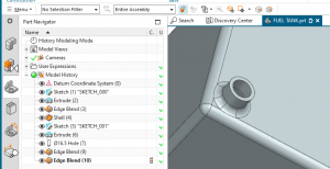
The NX Part Navigator is like a map of your CAD design, providing you with a visual representation of the structure of your models. It helps you manage components, navigate complex designs, and make design changes efficiently. Here, are some of its essential features: 1. Time Stamp Order: At the heart of the NX Part...
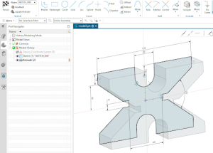
The Sketch Task Environment is a separate app within the modeling application. It will only create 2D entities. You will need to finish the sketch (checkered flag) to have access to the design application tools. https://www.youtube.com/watch?v=MjkswAHy1qs&feature=youtu.be When returning to edit an existing sketch, there are two options: 1) Edit and 2) Edit with Rollback. Edit...
Ctrl + E The NX Expressions Editor in Siemens NX allows users to create and manage parametric relationships within their designs. With the Expressions Editor, designers can define mathematical formulas, equations, and logical conditions to control the behavior of dimensions, features, and other design elements. This enables dynamic updates and automatic adjustments when changes are...
In Siemens NX, the category of "associative copy commands" represents a set of tools designed to create copies or duplicates of geometric elements, features, or entire components while maintaining a dynamic and associative link between the original and the copied entities. This means that any changes made to the original item will automatically propagate to...
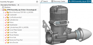
Assemblies are collections of one or more individual part files. In NX assemblies are the same file type as models (.PRT files). Assembly strategies vary, but in general, assemblies can be created from the bottom-up by assembling previously constructed models, or the approach can be top-down in which models are created within the context of...
(NX 2212 Documentation) Siemens NX offers part family functionality that enables users to efficiently manage and create variations of similar parts within a product family. Part families consist of a group of related components that share common features, dimensions, and design intent. With the part family functionality in Siemens NX, designers can define a master...
Curves in NX are powerful geometric elements. They can exist in 2D or 3D, and often form the framework for other features. Making high quality curves is essential to creating high quality surfaces and solids.
NX surface modeling in Siemens NX offers tools and capabilities for creating complex and organic surface geometries. With NX surface modeling, designers can craft smooth and precise surfaces that accurately represent the desired shape of a product or component. The software provides a comprehensive set of surface creation and manipulation tools, allowing designers to create...
Drafting (video) Assembly/Master Model Revision (TBD) Sheets Dimensions Ordinate Dimensioning Single (video) Multiple (video) Views Annotation Note: Drafting Standards can be made by going to File -> Utilities -> Customer Defaults -> Drafting Generally, NX drawings are created using the master model approach. While this is not strictly necessary, it increases design flexibility and improves...
https://youtu.be/KyKqzlygEao
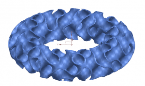
Implicit modeling is a technique used in computer graphics, computer-aided design (CAD), and computer-aided engineering (CAE) to create and manipulate 3D geometry. Unlike explicit modeling, where you directly define the individual components of a model, implicit modeling focuses on describing an object's shape through mathematical functions and constraints. In implicit modeling, objects are represented by...
JT is an openly published data format, widely used for communication, visualization, digital mockup and a variety of other purposes at most of the world's leading manufacturing companies. JT has been accepted by ISO as an International Standard for 3D visualization. Additionally, many adopters use JT as a process format for workflows such as data...
https://www.youtube.com/watch?v=de6pnH5dhpo Adjust your sheet metal preferences (or customer defaults) before starting.
This NX video tutorial series is designed to provide a solid foundation in using Siemens NX software...
This video introduces the NX interface. It is intended as a quick-start guide to familiarize new users...
This video introduces the typical workflow of going from a 3D solid model to a 2D working drawing using...
In the NX Modeling application, the Expressions Editor is a tool that allows users to create and manage...
In this video the core of the M40 valve needle is modeled. The sketch is fully defined and revolved....
This video builds on Tutorial 4A. This video covers how to add features such as edge blends, chamfers,...
In this video the needle valve needle is completed by adding a sketch, extruding it, and creating a...
Sketch
Fully define sketch
Extrude (or Revolve, Sweep)
Add Detail Features
Document...
The Master Model concept is a fundamental approach in product design and development, often utilized...
Every NX file is defined as either an inch or millimeter file. Once the file has been created, it is...


