Geometric Dimensioning and Tolerancing (GD&T) is a system of symbols and standards used in engineering drawings and models to specify the required form, size, orientation, and location of parts and features. It is an important tool for ensuring the interchangeability, functional accuracy, and reliability of manufactured components. GD&T is defined by the American Society of Mechanical Engineers (ASME) in the ASME Y14.5 standard, which provides a comprehensive set of guidelines and symbols for communicating the geometric requirements of parts and assemblies. The use of GD&T can help to reduce misinterpretation, reduce scrap and rework, and increase the efficiency of the manufacturing and inspection processes. By using GD&T, engineers and manufacturers can communicate their design intent more clearly and accurately, leading to improved quality, cost savings, and increased productivity.
Geometric Dimensioning and Tolerancing (GD&T)
Working outline
I. Introduction to Geometric Dimensioning and Tolerancing (GD&T)
A. Definition and purpose of GD&T
B. Overview of ASME Y14.5 standards
C. Benefits of using GD&T
D. Types of dimensioning and tolerancing methods
E. Overview of GD&T symbols, terms and concepts
II. Datum Reference Frame (DRF)
A. Definition and purpose of datums
B. Types of datum reference frames (DRF)
C. Datum selection and specification
D. Use of datum targets and datum features
E. Understanding of datum shift
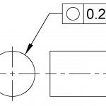
III. Feature Control Frames
A. Definition and purpose of feature control frames
B. Types of feature control frames
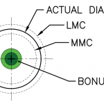
C. MMC and LMC concepts
D. Position and profile tolerancing
E. Diameter, radius and circular runout tolerancing
IV. Symbols and Definitions
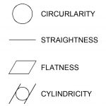
A. Overview of GD&T symbols and definitions
B. Explanation of the 14 GD&T symbols and their usage
C. Overview of functional gages and inspection methods
D. Understanding of limit gaging and statistical process control
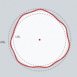
V. Form, Orientation, and Runout Tolerances
A. Definition and purpose of form and orientation tolerances
B. Types of form and orientation tolerances
C. Explanation of cylindricity, roundness, perpendicularity, and parallelism
D. Overview of runout tolerances and their applications
E. Understanding of total runout and its applications
VI. Dimensioning Principles
A. Overview of the principles of dimensioning
B. Types of dimensions and their usage
C. Explanation of tolerances, fits, and clearances
D. Overview of tolerance stacking and its effects
E. Understanding of Datum shift and its effect on tolerances
VII. Advanced Topics in GD&T
A. Overview of tolerance zones and their applications
B. Understanding of bonus tolerance and its usage
C. Explanation of composite profiles
D. Overview of parallelism in orientation tolerance
E. Understanding of the use of controlled radii and controlled arcs.

")