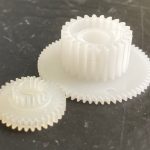
Power transmission and motion control form the backbone of nearly every mechanical system. While individual machine elements—such as gears, shafts, and bearings—are often studied in isolation, their true function emerges only when considered as part of a system that must both transfer energy and constrain motion in predictable ways. This category brings together those elements and features that determine how motion is generated, guided, limited, and delivered.
At its core, power transmission involves the movement of mechanical energy from a source to a point of use. This may be as simple as a rotating shaft driven by an electric motor, or as complex as a multi-stage gearbox distributing power through several paths. Motion control, by contrast, focuses on how that movement is constrained. A shaft may be required to rotate but not translate, or to slide axially while transmitting torque, or to remain fixed in both respects. These requirements define the selection and arrangement of machine elements.
A useful way to understand this category is to consider motion in terms of two fundamental degrees of freedom associated with a shaft: rotation and translation along its axis. Most mechanical components in this domain exist to either allow or prevent one or both of these motions. For example, a plain bearing allows rotation while supporting the shaft radially, whereas a thrust bearing resists axial movement. A spline permits torque transmission while allowing axial sliding, while a shaft collar prevents axial movement without interfering with rotation. By combining such elements, a designer can achieve precise control over how a component behaves within a system.
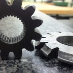
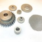
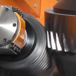
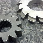
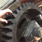
Shafts serve as the primary carriers of mechanical power in many systems. They are typically cylindrical and are designed to transmit torque while supporting attached components such as gears, pulleys, or couplings. The performance of a shaft is closely tied to its geometry and surface features. Shoulders provide axial location, grooves accommodate retaining rings, and keyways or splines enable torque transfer to mating components. Threads, tapers, and flats may also be introduced to facilitate assembly, adjustment, or locking.
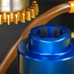
The interface between a shaft and a mounted component—often referred to as the shaft–hub connection—is a critical design consideration. These interfaces must transmit torque reliably while meeting specific requirements for assembly, disassembly, and alignment. Common solutions include keyed joints, splined connections, interference fits, and clamping devices. Each approach reflects a different balance between strength, precision, manufacturability, and serviceability. For example, an interference fit provides a clean, concentric connection with high torque capacity but may complicate maintenance, while a keyed joint is easier to assemble and disassemble but introduces stress concentrations.
Axial positioning is managed through a combination of features and devices designed to restrain movement along the shaft. Integral features such as shoulders may be combined with separate components including retaining rings, threaded fasteners, spacers, and shaft collars. These elements establish fixed locations for rotating components, ensuring proper alignment and load distribution. In many cases, axial retention must be achieved without interfering with rotation, requiring careful attention to contact surfaces and clearances.
Couplings extend the concept of shaft connection by linking two shafts together, often accommodating misalignment or damping vibration. Rigid couplings maintain precise alignment but transmit all loads directly, while flexible couplings—such as jaw, beam, or Oldham designs—introduce compliance to absorb misalignment and reduce stress. Clutches and brakes further expand the system by enabling controlled engagement or disengagement of motion, allowing power to be transmitted selectively or dissipated as needed.
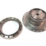
Bearings play a central role in motion control by supporting shafts and reducing friction. Plain bearings provide a simple, robust solution for many applications, relying on sliding contact and lubrication. Rolling element bearings, including ball and roller types, reduce friction further and can support both radial and axial loads. Specialized bearings, such as thrust bearings or linear bearings, are used where motion must be constrained in specific directions while remaining free in others.
Linear motion systems represent an extension of these principles beyond rotation. In such systems, components like linear bearings, guide rails, and ball screws are used to achieve controlled translation. A ball screw, for example, converts rotational motion into linear motion with high efficiency and precision, making it a key element in many automated systems.
Taken together, the elements within this category provide a framework for understanding how mechanical systems function at a fundamental level. Rather than viewing components in isolation, it becomes possible to analyze a system in terms of how it manages rotation and translation, how it transmits forces, and how it maintains alignment and control. This perspective not only supports effective design but also aids in troubleshooting, maintenance, and the interpretation of engineering drawings and specifications.
In practice, successful power transmission and motion control depend on the careful integration of these elements. Choices made at the level of a single feature—such as the selection of a fit or the inclusion of a keyway—can influence the performance of the entire system. For this reason, the study of this category is not limited to individual components, but extends to the relationships between them and the constraints they impose.