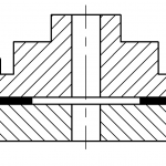
A section view in engineering graphics is a way of showing what the inside of an object looks like by imagining that part of it has been sliced away. Instead of relying on hidden lines to suggest internal features, a section view removes part of the object visually and displays what remains, as if the observer is looking straight into the cut. This approach allows the interior details—like holes, pockets, ribs, and complex shapes—to be shown more clearly and accurately.
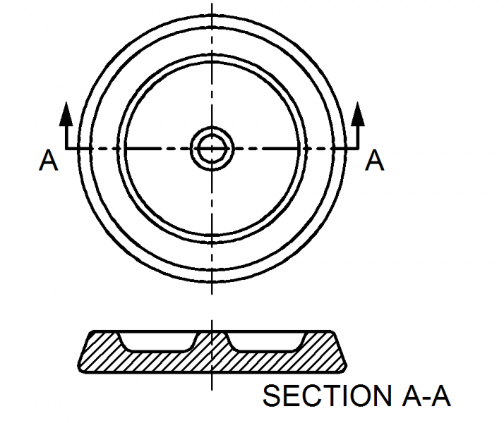
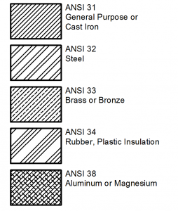
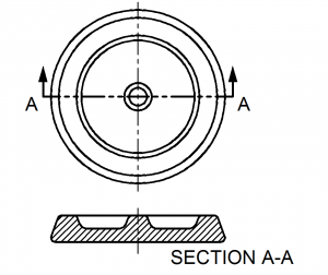
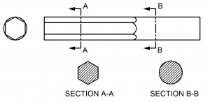
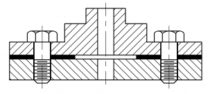
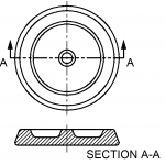
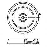
To create a section view, an imaginary cutting plane is passed through the object, and everything in front of that plane is removed from view. The surface where the cut occurs is typically filled with hatching lines (also called section lines), which indicate solid material. The orientation of the cutting plane can vary depending on what features need to be revealed, and it’s often labeled with arrows and letters on the standard orthographic views to show the direction from which the section is observed.
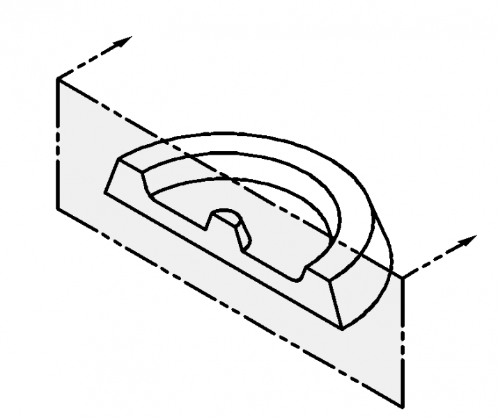
Section views are especially useful when dealing with objects that have complicated interiors or multiple overlapping features. Rather than interpreting a maze of dashed lines, the viewer can see the geometry as if the object were physically cut open. This not only improves clarity but also supports more accurate fabrication, inspection, and communication of design intent.
A Physical Example of a Section View
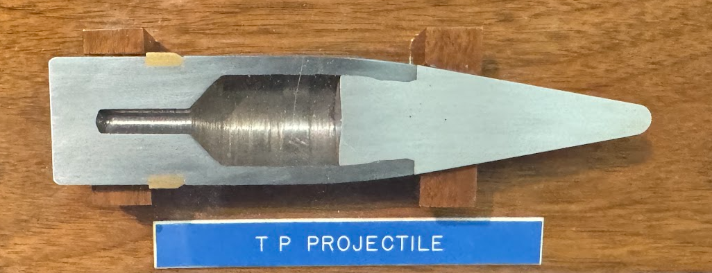
A useful way to understand a section view is to compare an engineering drawing with an object that has actually been cut apart. The projectile shown below is a TP (Target Practice) projectile photographed at the Air Force Armament Museum near Eglin Air Force Base in Florida. The museum specimen has been cut lengthwise through its center, exposing the internal construction of the projectile.
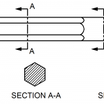
In an engineering drawing, we can represent this same idea without physically cutting the object. The illustration below shows two orthographic views of the projectile. In one view, the line labeled A–A identifies the location of an imaginary cutting plane passing through the projectile. The arrows at the ends of the cutting-plane line indicate the direction in which the resulting section is viewed.
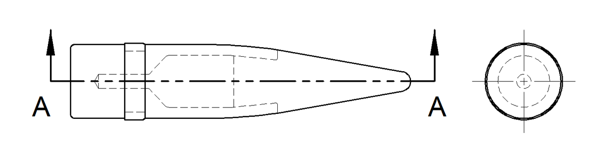
To produce the section view, imagine cutting the projectile along plane A–A and removing the portion between the observer and the cutting plane. Looking directly at the newly exposed surface produces SECTION A–A, shown below.
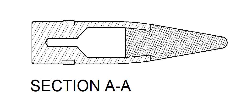
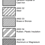
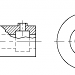
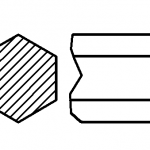
The section view reveals the internal shape much more clearly than an ordinary exterior view could. The diagonal section lines, or hatching, identify the areas where the cutting plane passes through solid material. Open areas are left unhatched. In this way, the drawing communicates essentially the same information that can be seen in the physically sectioned museum specimen.
This comparison illustrates the basic principle behind a full section view: the object does not actually need to be cut. The cutting plane is an imaginary drafting convention that allows the designer to show the object’s internal construction clearly and unambiguously.